AONE ENCOR Study Group - VRF Lab
I am part of The Art of Network Engineering ENCOR study group. If you are unfamiliar with The Art of Network Engineering, they are a podcast for Network Engineers who have cultivated a wonderful community of IT professionals. Part of that community is on Discord and in that Discord are a number of folks studying for certifications such as the CCNP ENCOR exam. Our study group met today on June 23rd, 2025 to discuss how we wish to proceed with our study group. Previously we were working our way through the ENCOR Official Cert Guide chapters. Now we are focusing on the CCNP ENCOR Exam topics that have the verbs “configure” and “troubleshoot” in them and prioritizing building labs that align with those topics. On June 30th, 2025 we will meet and work on the first two exam topics listed with the “configure” verb:
2.2 Configure and verify data path virtualization technologies
2.2.a VRF
2.2.b GRE and IPsec tunneling
In preparation for next week, I have gone forward with building out a VRF lab as well as some generalized lab instructions. Here are the Lab Instructions:
VRF Lab:
Create a router with two vrf instances (one including the global routing table).
Assign your named vrf instance to interface 2.
Create and assign an IP address scheme that overlaps on interface 1 and interface 2.
Create and assign a separate IP address scheme that does not overlap on interface 3.
Create hosts on interfaces 1, 2, and 3. Assign these hosts IP addresses.
Verify that hosts on interface 2 cannot ping hosts on interfaces 1 and 3.
Verify that hosts on interface 1 and 3 can ping each other.
Verify both the global route table and your vrf route table.
Here is a link to a YAML file that shows how I completed the lab. I think leaving the lab instructions vague leaves people room to be creative with how they accomplish the lab (this is actually just an excuse for my poor lab writing skills).
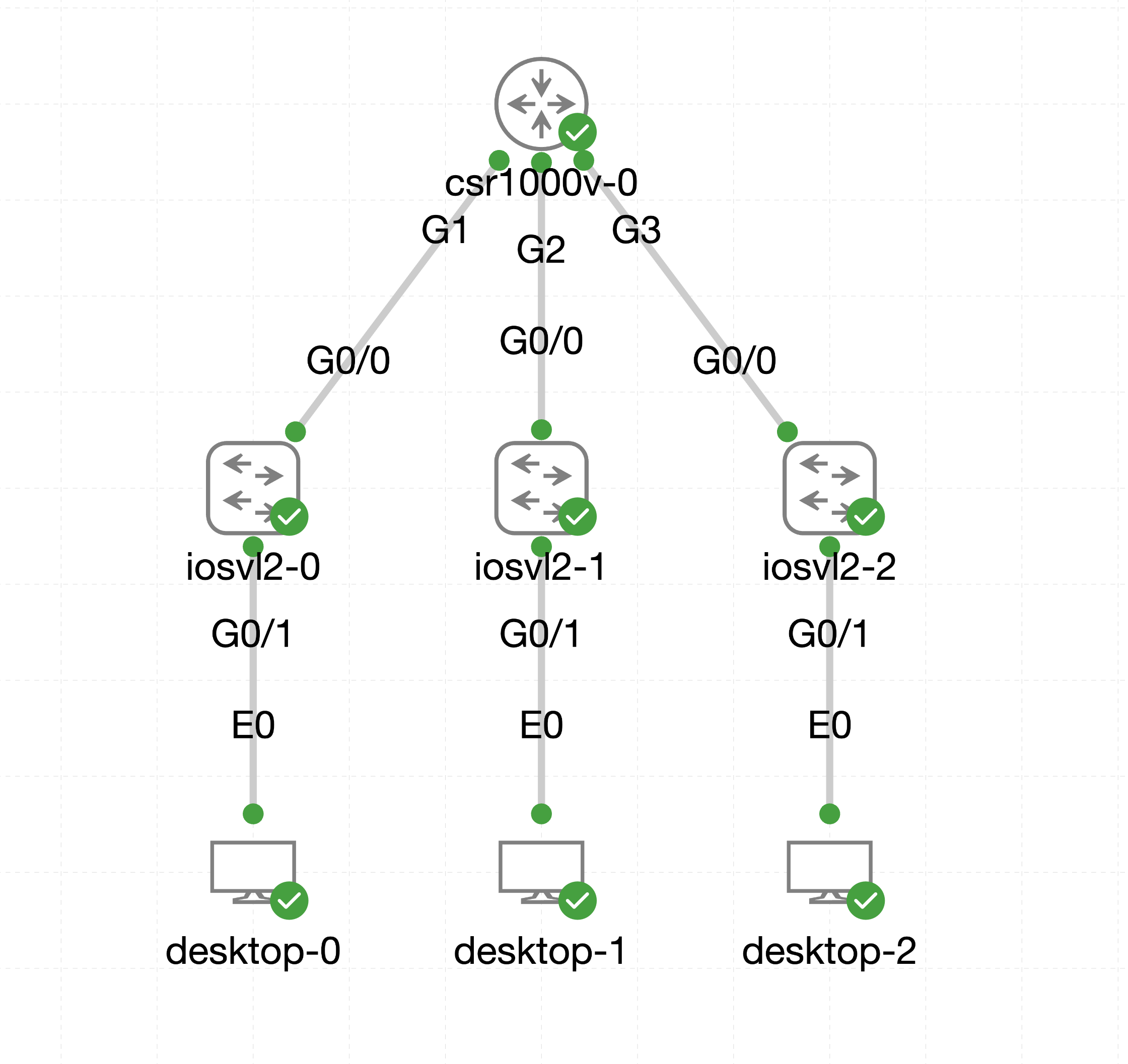
1 CSR Router with 3 Connected L2 Switches and Three Linux Desktops
Above is the lab that I built out using the above lab instructions. In this lab I created a csr1000v router and assigned the following configuration:
I created a vrf instance name MGMT using the ipv4 address family:
vrf definition MGMT
address-family ipv4
I then assigned the vrf instance MGMT to interface 2 as well as subinterface 2.10:
- interface GigabitEthernet 2
- vrf forwarding MGMT
- ip address 192.168.1.1 255.255.255.0
- interface GigabitEthernet 2.10
- encapsulation dot1q 10
- vrf forwarding MGMT
- ip address 192.168.10.1 255.255.255.0
You'll notice below this is the same IP scheme that I gave interface 1. If I failed to assign the VRF intstance to interface 2 it would have errored out and stated that the interface subnets and IP's overlap.
- interface GigabitEthernet 1
- ip address 192.168.1.1 255.255.255.0
- interface GigabitEthernet 1.10
- encapsulation dot1q 10
- ip address 192.168.10.1 255.255.255.0
On interface 3 I assigned a non-overlapping IP scheme into the global vrf instance.
- interface GigabitEthernet 3
- ip address 192.168.2.1 255.255.255.0
With the above interfaces created and configured, I created three layer 2 switches with VLAN's 1 and 10, set interface G0/0 as a trunk port with native vlan 1 and allowed VLAN's 1 and 10. Lastly I set interface G0/1 as an access port with VLAN10 tagged.
- interface GigabitEthernet0/0
- switchport trunk allowed vlan 1,10
- switchport trunk encapsulation dot1q
- switchport mode trunk
- !
- interface GigabitEthernet0/1
- switchport access vlan 10
I then added a Linux desktop to each switches G0/1 port. I then acccessed the Desktop's VNC connection to then use the terminal to configure the eth0 interface on each desktop.
Desktop-0
sudo ifconfig eth0 192.168.10.3 netmask 255.255.255.0
sudo route add default gw 192.168.10.1 eth0
Desktop-1
sudo ifconfig eth0 192.168.10.4 netmask 255.255.255.0
sudo route add default gw 192.168.10.1 eth0
Desktop-2
sudo ifconfig eth0 192.168.2.3 netmask 255.255.255.0
sudo route add default gw 192.168.2.1 eth0
NOTE: I believe the correct way to assign this information is to write in /etc/network/interfaces but my nano/vi skills are lacking. I believe if you do the above method it will not retain the info on stop/start of the lab.
For step 7, I conducted the following ping tests:
- Desktop-0 ping 192.168.10.4 - FAIL
- Desktop-0 ping 192.168.2.3 - SUCCESS
- Desktop-1 ping 192.168.10.3 - FAIL
- Desktop-1 ping 192.168.2.3 - FAIL
- Desktop-2 ping 192.168.10.3 - SUCCESS
- Desktop-2 ping 192.168.10.4 - FAIL
For step 8, I ran the following show commands:
show ip route
192.168.1.0/24 is variably subnetted, 2 subnets, 2 masks- C 192.168.1.0/24 is directly connected, GigabitEthernet1
- L 192.168.1.1/32 is directly connected, GigabitEthernet1 * 192.168.2.0/24 is variably subnetted, 2 subnets, 2 masks
- C 192.168.2.0/24 is directly connected, GigabitEthernet3
- L 192.168.2.1/32 is directly connected, GigabitEthernet3 * 192.168.10.0/24 is variably subnetted, 2 subnets, 2 masks
- C 192.168.10.0/24 is directly connected, GigabitEthernet1.10
- L 192.168.10.1/32 is directly connected, GigabitEthernet1.10
show ip route vrf MGMT
192.168.1.0/24 is variably subnetted, 2 subnets, 2 masks- C 192.168.1.0/24 is directly connected, GigabitEthernet2
- L 192.168.1.1/32 is directly connected, GigabitEthernet2 * 192.168.10.0/24 is variably subnetted, 2 subnets, 2 masks
- C 192.168.10.0/24 is directly connected, GigabitEthernet2.10
- L 192.168.10.1/32 is directly connected, GigabitEthernet2.10
From the above commands we can see that both the global routing table and the vrf instance MGMT have the 192.168.1.0/24 subnet directly connected and yet clients on interface 2 are unable to communicate with clients on interfaces 1 and 3.
I hope you came up with a lab that looks different than mine but achieves the same results of creating separate logical route tables on a single router. If you find any errors in my lab above, please let me know via the comments as this is my first time writing.